

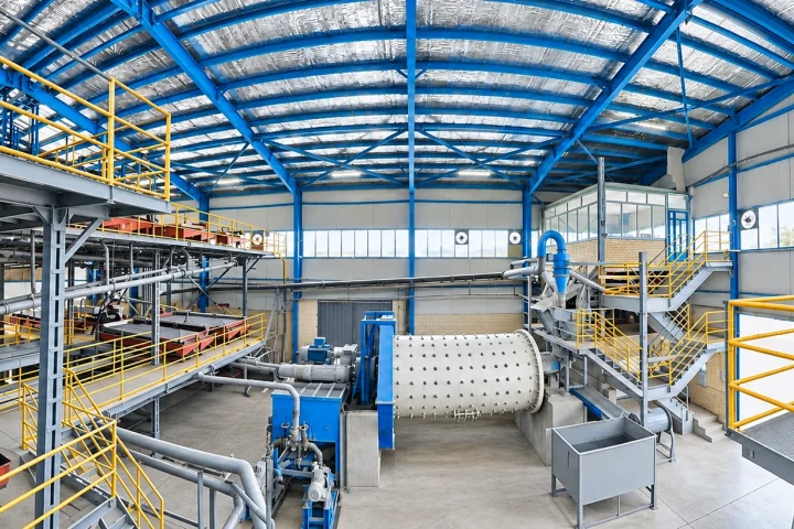
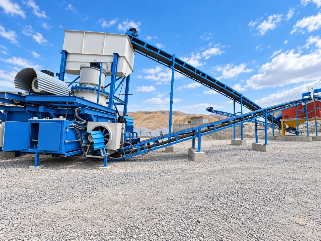
Define the equipment duty before the geometry
Throughput alone is not a complete design input. Particle size, bulk or slurry density, solids concentration, abrasion, corrosion and operating temperature can change the appropriate geometry and materials. Startup, blockages, cleaning and transient loading also need to be considered.
Zarfaravar starts equipment engineering by connecting these process requirements to a clear datasheet. This gives the process designer, mechanical engineer and fabricator a common basis and makes unresolved inputs visible before manufacturing commitments are made.
- Normal and peak feed conditions
- Material properties and expected wear mechanisms
- Loads, torque and power requirements
- Cleaning, isolation and maintenance access
Sizing crushing, conveying and separation equipment
Crushers, mills, screens, conveyors, pumps and separation units do not share one sizing rule. Each has its own performance envelope and control limitations. Oversizing can increase capital cost and energy demand or make operation less stable; it is not automatically a safer choice.
Sizing should be checked against the circuit balance, effective operating hours, recirculation and feed variability. Mechanical interfaces, motor selection, instrumentation and the capacities of adjacent units then need coordinated review.
Choose materials for the actual failure mechanism
Abrasion, impact and corrosion require different responses. A more expensive alloy cannot compensate for an unsuitable flow path or an inaccessible wear component. Material selection should therefore consider velocity, impact angle, duty and replacement logistics together.
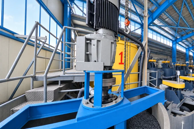
The design scope can identify wear zones, replaceable liners and accessible fastening arrangements. Standardising suitable parts and planning lifting access may reduce maintenance interruption more effectively than a small saving in fabrication cost.
- Wear and corrosion zones
- Replaceable components and liner access
- Handling weight and lifting arrangements
- Spares availability and standardisation
Use 3D coordination to resolve real interfaces
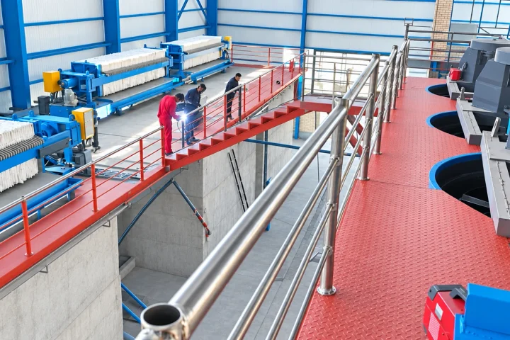
A model is useful when it answers practical questions: can a motor be removed, does a pipe obstruct a lifting route, and can an operator reach the inspection point? These checks need the surrounding structure and services, not just the machine in isolation.
Zarfaravar equipment design connects the model and general arrangement to fabrication drawings, dimensions, tolerances and the bill of materials. The required drawing detail depends on whether the scope is concept selection, procurement support or manufacturing engineering.
Standard equipment, custom design or modification?
A proven standard unit can be the right answer when it meets the duty and interface requirements. Custom engineering becomes useful when material behaviour, layout or maintainability creates a genuine constraint. Modification of an existing unit also needs its condition and operating history to be understood.
The comparison should include technical suitability, delivery time, fabrication capability, support and lifecycle cost. The aim is a defendable choice, not customisation for its own sake.
From design documents to fabrication acceptance
A handover package should make the intended checks clear. Depending on the equipment and scope, these may include material identification, dimensions, assembly, alignment and agreed functional tests. Applicable requirements must be defined for the particular item rather than copied indiscriminately.
Share existing drawings, operating data, photographs and the failure history with Zarfaravar when requesting redesign. These inputs help distinguish a design problem from an operating, installation or maintenance issue and focus engineering effort where it is needed.